Weekly Assignment
Computer Controlled Machining
This week also have two assignment one is Individual assignment and other
is group
Individual assignment
make (design+mill+assemble)
something big.
Group assignment
Do your lab's safety training ,test run out,
alignment, speeds, feeds,materials, and tool paths for your machine. click here
CNC
A CNC (computer numeric control) tool is used in prototyping and full production for cutting, carving, machining and milling in a variety of materials including wood, mdf, plastics, foams and aluminum.With a ShopBot CNC tool, you use the included software to design your parts on your personal computer, then, like a robot, the computer controls the cutter to precisely cut your parts. In the past, CNC tools were strictly industrial tools only used in large factory settings. Now, all the types of computer-driven tools that create things by cutting material away
(such as CNCs or laser cutters) or building up material in layers to create an object (3D printing)
are called digital fabrication tools. ShopBot's innovations in CNC technology
have made these powerful tools affordable for individuals and small shops. know more
Major Parts/Units of CNC Shopbot
To know more guide to shop-bot
To Know assembling Guide

-
Control Box : The control box is the “brain” of the machine.
It contains a control board, motor drivers, and other numerous electronic components that allow the tool to move with precision, accuracy, and power. It connects to your PC through a single USB cable.

-
Power Switch : To the machine ON/Off,there is a red switch located on the right side of the machine near to the control box.
-
The interlock key: Is located on the left side of the power switch. The function of this key is to activate the spindle.
-
VFD: This box controls speed and power for your spindle.
-
Spindle: The CNC spindle is the heart of any mill.
It consists of a rotating assembly with a taper where tool holders may be installed.
-
Bed: The bed is the area where we place the material.
- Emergency Stop Switch: It is used for stopping
the machine during emergencies.
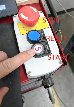
- Reset switch: It is for the initial stage to have the clean Micro Controller and ready to process the data from the computer's serial communication.
The machine will not communicate with the computer until you reset the drivers.
- Start Button: It is for starting the spindle before the process of the cutting starts.
-
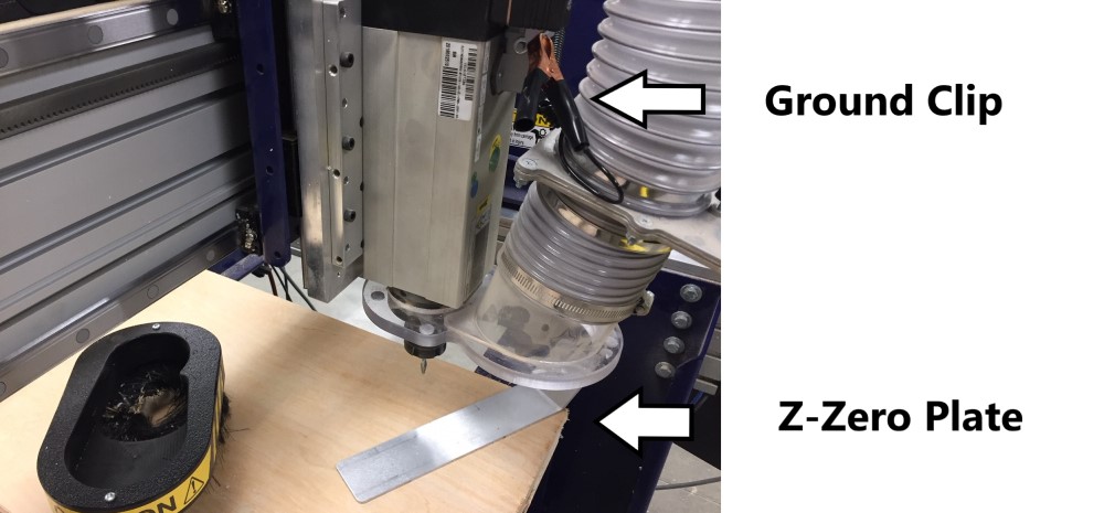
Z Zero Assembly Plate: The ShopBot CNC routers are equipped with a zero plate. This is a conductive metal plate with a thickness that is programmed into the machine's system.
We can run a command that will move the tool down until it touches the plate,
then the software will automatically subtract the plate thickness and give
you an exact Z height.

-
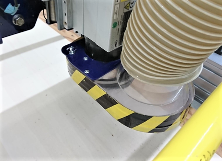
Dust collector: It is as important as any other tool. It’s not just important for dust collection to keep the machine clean), but it is also important for your health. It protects the lungs from fine wood particles, chemicals, fungi and bacteria.
Materials:
We can use a variety of materials including :
Wood.
MDF.
Plastics.
Foams.
Aluminum.
To get more information about Shopbot CNC machine click on this link: Shopbot.
Cutting Tools:
CNC machining utilizes a subtractive process that uses cutting tools. There are two basic kinds of cutting tools for the ShopBot:
- Drill bits : These kinds of bits are the same bits used in a hand drill or drill press. They are only for drilling holes, and only work when moving straight down.

- End mills & router bits: These bits are designed to cut while moving sideways through the material.
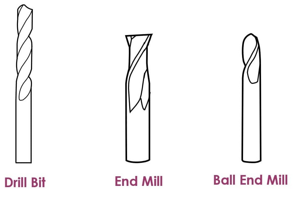
Each end mill has a tip which is shaped and designed for a particular purpose. Some common cutter shapes are ball nose, fish tail, surface planing, v-carving, and straight.
- Ball Nose mills : Produce a rounded pass and are ideal for 3D contour work.
- Fish tail cutters: Produce a flat surface.
- V-bits : Produce a “V” shaped pass and are used for engraving, particularly for making signs.
Cutting tools have two parts:
- The Shank: is the section that goes into the tool holder.
- The Flute: is the cutting edges of the bit.

There are so many options out there for router bits that it may be difficult to decide which one is the right router bit for our application. Some bits are available as:
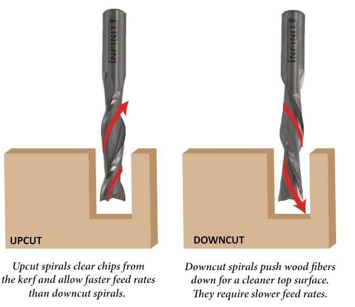
- Up-cut: It is very efficient in evacuating chips up and out of the cut. It will leave a very clean finish at the bottom of the workpiece, but will leave a rougher surface on the top of the surface.
- Down-cut: It is best to use a down cut bit for through cuts, as a down cut bit pushes the chips down into the cut. Down cut bits will leave a very clean cut on the top of the workpiece, but may leave a rougher finish on the bottom.
The difference between an up cut router bit and a down cut router bit is the direction of the flutes.
- Compression spiral: A combine bit (down-cut on top & up-cut on the bottom) designed to cut all the way through sheet goods in a single pass. Compression bits leave a beautiful smooth finish on both sides of the workpiece being cut.
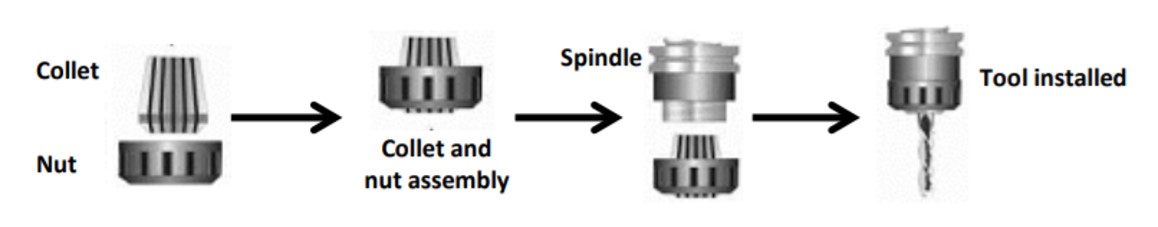
To insert the tooling :
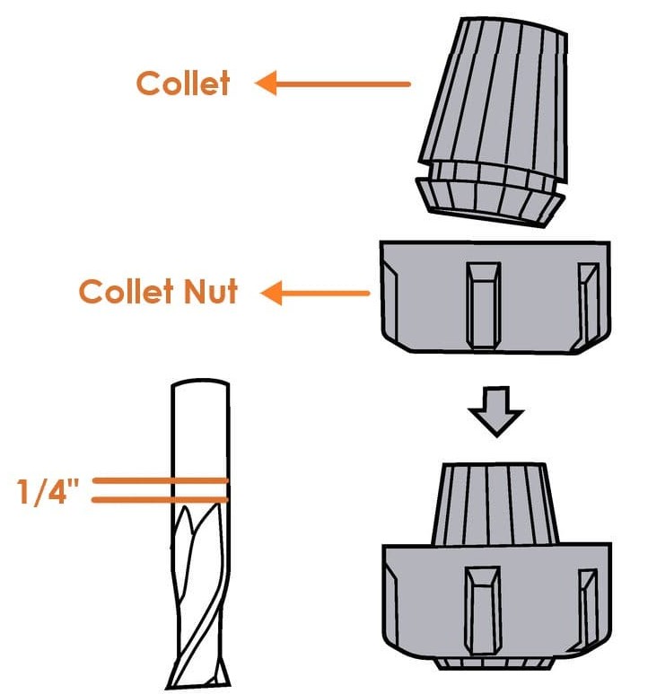
1. Select the appropriate collet for your tool. The shank of the end mill must be the same size as the collet.
2. Push it into the collet nut until it clicks.
3. Put the collet nut onto the spindle.
4. Insert the tool into the hole in the collet, and push it in until the flutes are almost touching the collet ( Keep ¼” space between the collet and the flutes).
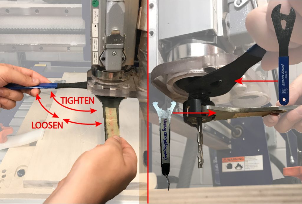
5. Hand tighten the collet holder on the spindle.CNC Machine Features:
- Feed: is the linear feed of the tool through the material.
- Speed: is the rotational frequency of the spindle which turns the bit.
The feeds and speeds are defined for each bit and material type within the toolpathing software.
- Pass Depth: Determines how much deeper the tool goes into the material with each pass.
- Stepover: Indicate how much the tool will overlap on each pass when rastering a pocket.

VCarve Software
What is VCarve software ?
A computer software called VCarve Pro is used to specify the type of carving required, the tooling details, cutting parameters and name for the tool path. It is also to control the path that the machine follows while cutting.
This is the interface of the VCarve :
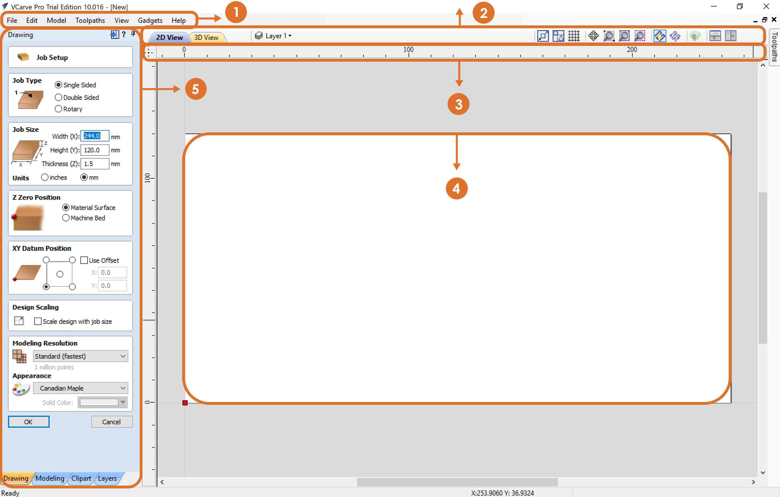
Vcarve has a very simple interface that contains the following:
1. Menu Bar : Clicking on any of the options on the menu bar (File, Edit etc.) will result in a drop-down menu appearing with choices related to that topic. Many of these are just an alternative way to access functions.
2. Navigation Toolbar : To switch between 2D view and 3D view. Beside that, you can manage layers and then you can find a view toolbar that can be useful and that will help you while you design.
3. Ruler : The Rulers are permanently displayed in the 2D view to help with positioning, sizing and alignment.
4. Job Area : It is the working space that contains all the designs.
5. Job Setup :
Job Type : To set what type of work you'll create. One-sided work or double-sided.
Job Size : To set the job size dimensions ( W , L , D ), which we need to come up with to know our design parts. I prefer to set the job size to be equal to the actual material dimensions. This will prevent us from wasting the material, and it will enable us know the exact location of each job. You can change the unit ( Inch or mm ). I prefer to use mm.
Z Zero Position : To set Z Zero position.
XY Datum Position: To set the origin point. By default is the lower left corner.
Modeling Resolution : To set resolution and color for the 3d objects.
To create a new document click on “OK”. Then you will get new panels.

6. Design Panel : All tools to design and modify designed objects. You can switch between a group of tools with tabs at the bottom of the design panel.
7. Toolpaths : To set the material setup and select the different types of toolpaths that you need for your design.
Material Setup :
Create tool paths:
Vcarve has the ability to do many types of toolpaths., I will explain the main toolpaths that we usually use in 2D designs :
Profile tool path: It provides the flexibility for cutting 2D shapes out on the material by following a closed path with optional tabs / bridges. It also ensures perfect edge quality.
What is Tabs (Bridges) ?
Tabs are added to open and closed vector shapes, and to hold parts in place when cutting them out of material.
There are 3 options to determine how the tool is positioned relative to the selected vectors:
- Outside : Calculates a profile toolpath around the Outside of the selected vectors.
- Inside : Calculates a profile toolpath around the Inside of the selected vectors.
- On : Calculates a profile toolpath On the selected vectors.
Pocket tool path: To remove materials from the interior of a path down to the specified depth.
Drilling tool path: Drilling allows the centers of selected closed vectors to be drilled to a specified depth.
To save the file:
- Save the tool paths (.shp file)
- Save the project. (.crv file)
For more information about VCarve software : Vcarve Pro User Manual
What is ShopBot Control Software?
This is the software that controls the CNC machines.
ShopBot control software interface:
The “Easy” Control Panel: This panel gives us access to essential machine information and controls.
The KeyPad: The KeyPad allows us to manually move the X,Y,Z axes of the machine.
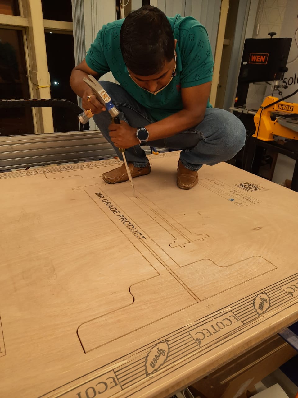
In this assignment, we have to make, design, mill and assemble something BIG. To start this assignment, there are steps that we have to follow to get the final product:
1. Design the geometry by using any design software, then export it out.
2. Import the design to Vcarve software then define all the tool paths that will control the shopbot.
3. Load the material, bit and set up the machine.
4. Control the machine by using ShopBot control software.
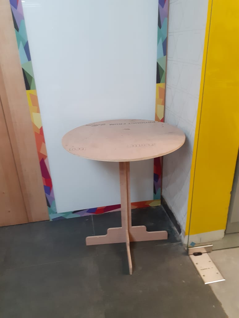
Once we have that all set, then we are ready to cut. We are going to run the files that we will go through to cut the part out and we will be done!
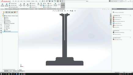
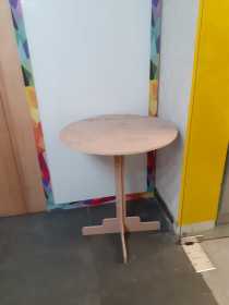
Designing
Using solid works I
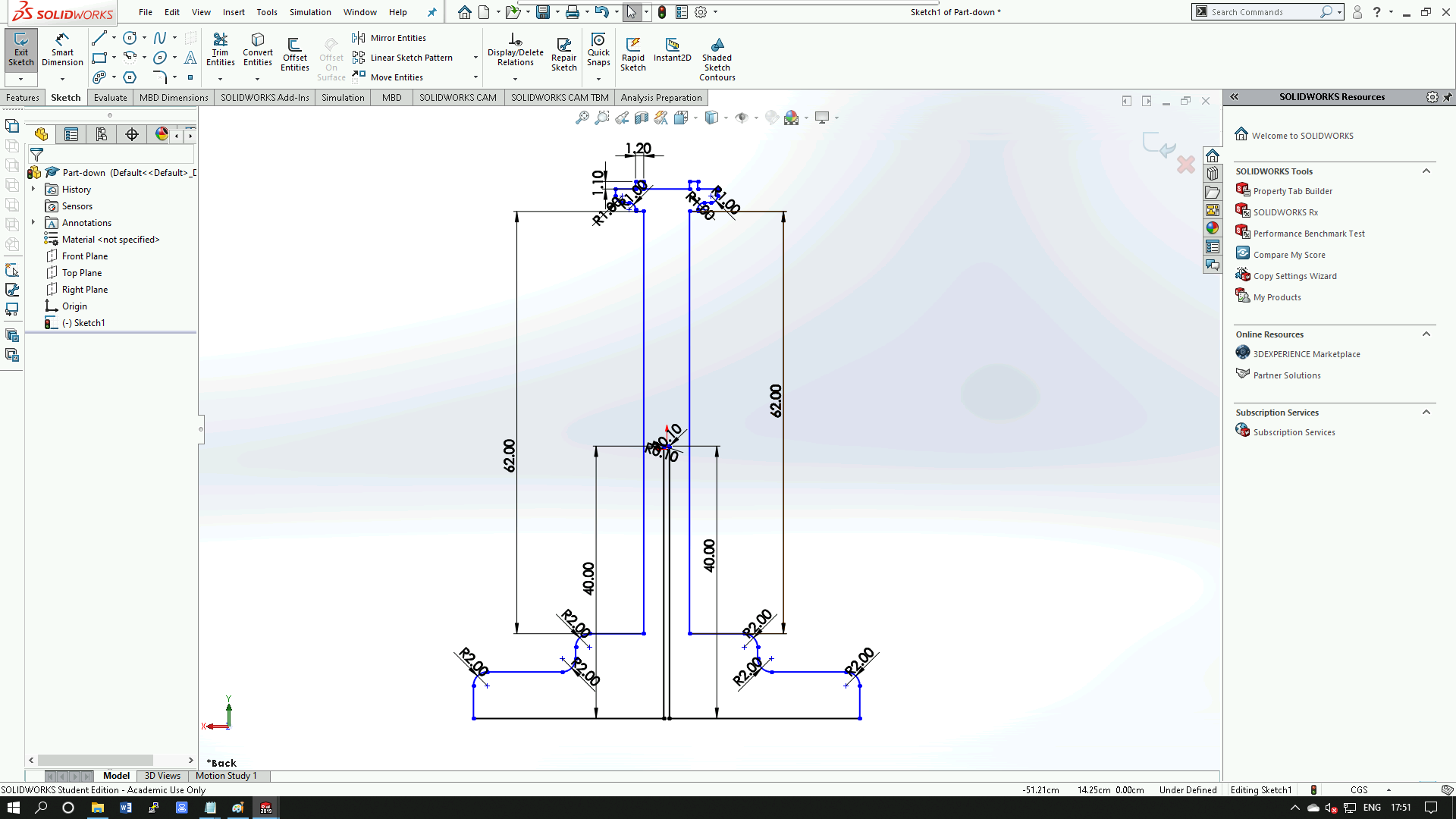
designed the structure for the table top and legs.initially i create sketch for the legs, i decided for
the fitting of two parts of table leg must fitted with press and table also table
top fit with leg by press.Here is the designing

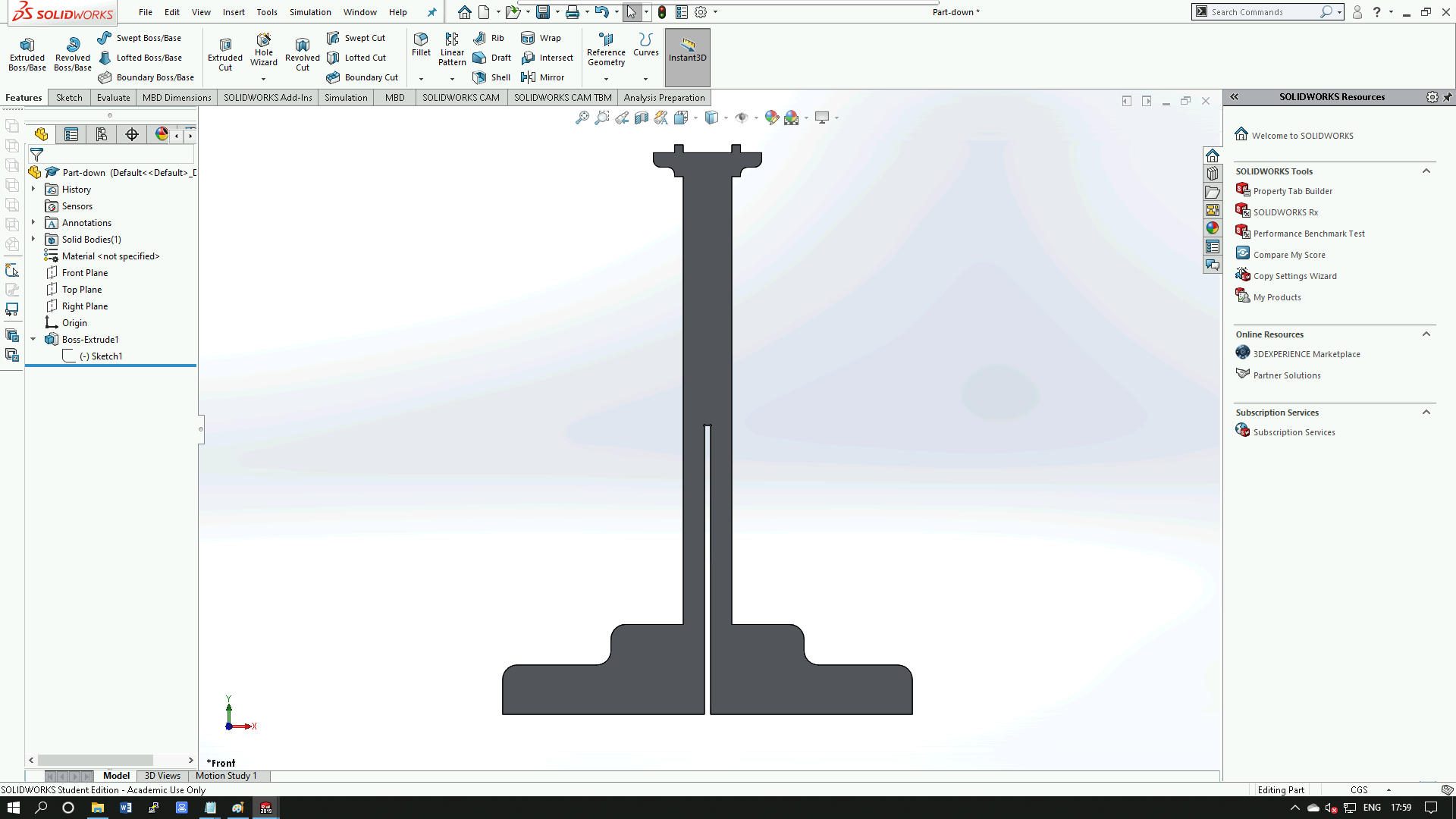
After sketch drawing then extruded
After completing the first part of the leg the second part leg sketch is as follow
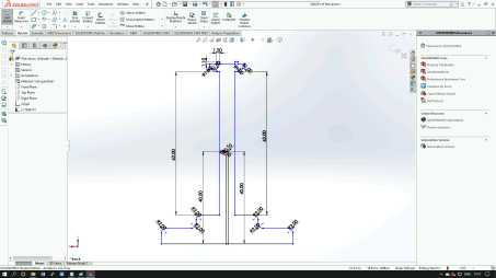
Complete the sketch drawing then exit the sketch and extruded

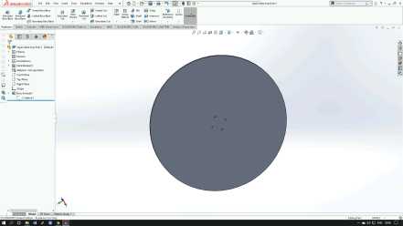
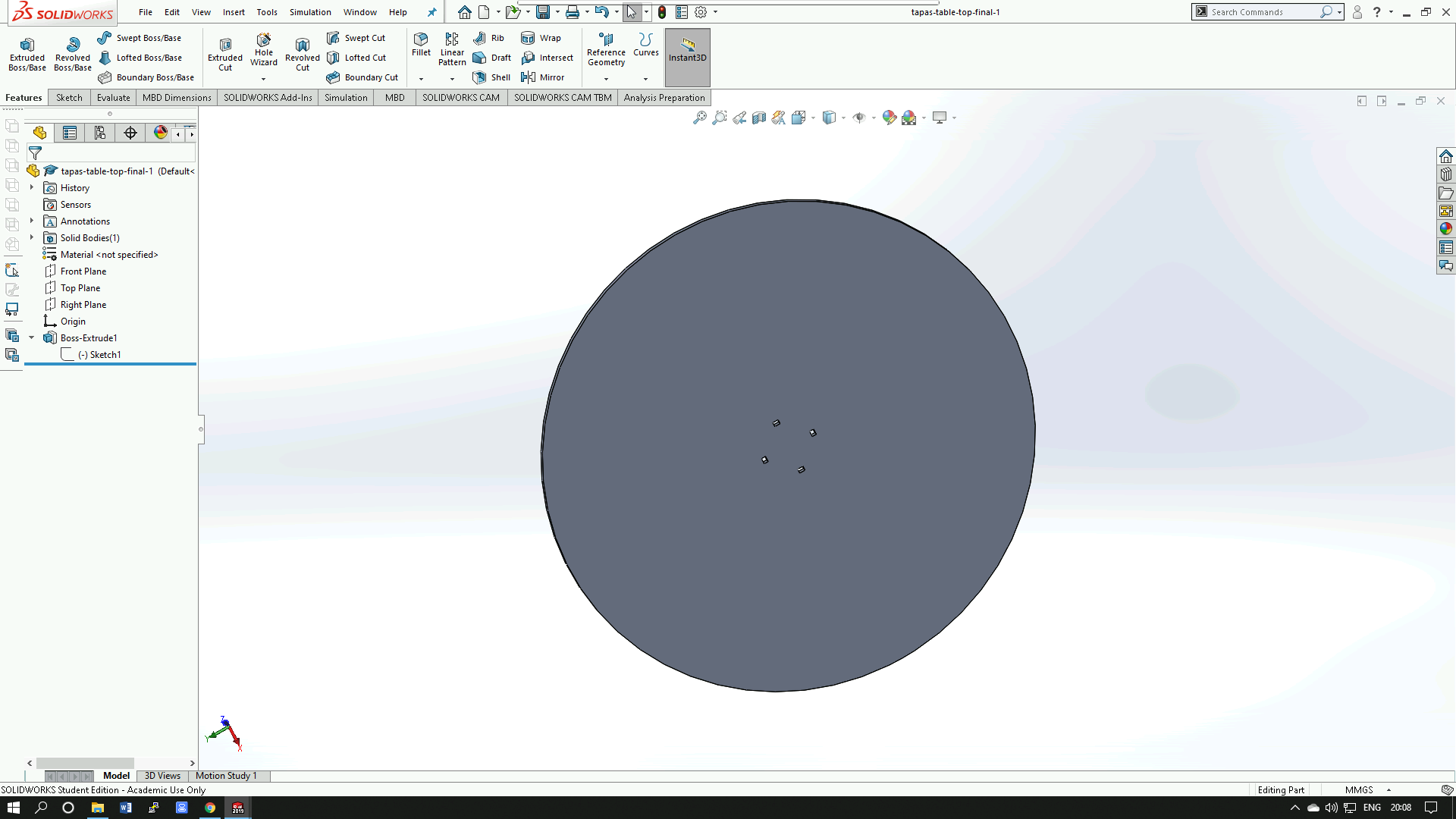
The designing of the two parts table legs are complete now the table top sketch is as follow
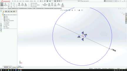
Complete the sketch drawing then exit the sketch and extruded
Setting the tool path
Before we start to mill, We have to first set the tool paths for milling various parts. In our lab we use the software 'Vcarve' for setting tool paths and to generate G-codes.
I uploaded my design which is a .dxf file into the vcarve software.
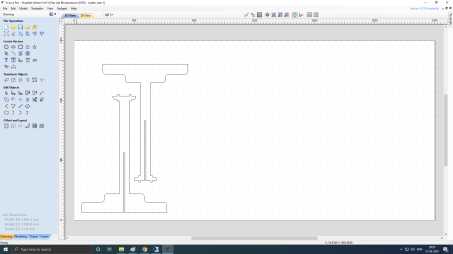
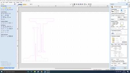
Make sure all the lines and vector paths of an object is joined. Select an object, and use
the toolpath window to set the toolpath for the job.as i using 12 mm plywood so the cut depth
12.3 mm otherwise the wood will not properly cut here is i have selected on in machine vector
Add tabs to the tool path, so that the parts don't move when cutting. don't put tab in corner or at curve port of
design
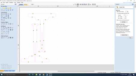
After Add tabs to the tool path, calculate with a profile name here is kept leg.check
the tool bit setting whether it is correct or not

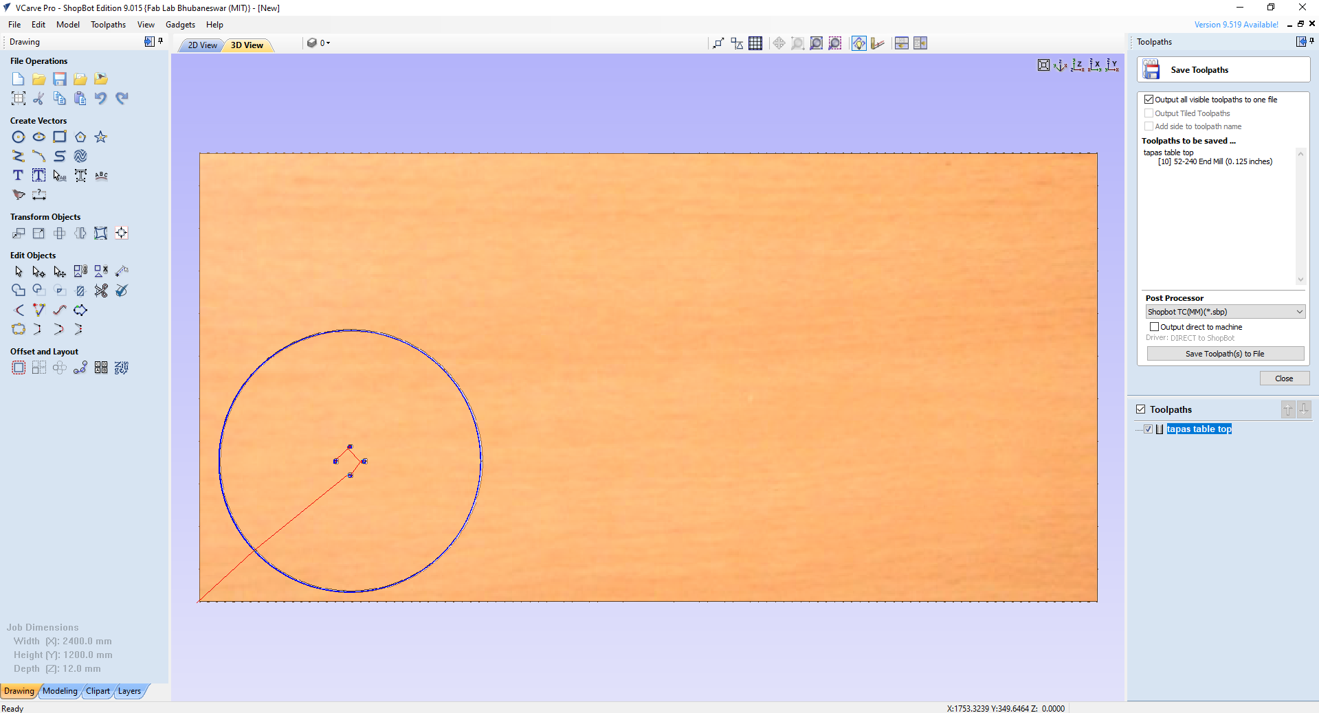
Reset preview and preview all tool path which acknowledge you to see the movement of bit at the time of cutting
and save the file into .sbp format
which will use for cut part at time of machine
i have to use Screw hole - Drill holes on the plywood board for mounting the board to bed.
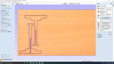
table top file for cutting.

Machine Setup
Switched on the control box, then opened the Shopbot 3 application. Its better to leave the spindle disengaged to be on the safer side.
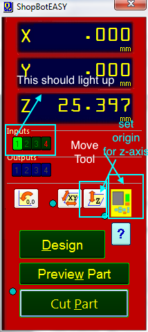
Click on the move tool, it should give a UI similar to the below image. Use the joysticks on the UI to move the spindle to set the origin. First set the x-y position and click the zero axes button,
you will see a pop up with checkboxes for all three axes. Select the x and y axes and click ZERO.
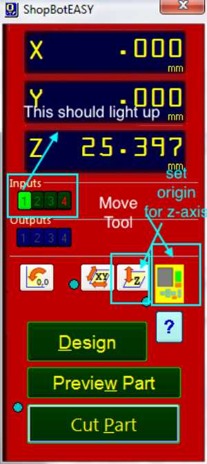

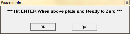
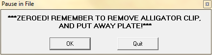
At this point, we have our x and y axes set to origin, now we need to set the z-axis. Use the plate on the spindle head to set the origin for z-axis. Make sure the Input lights up when making contact with the aligator clip. After that click the z-axis button and place the plate on the bed, bottom to the drill bit.
The prompts the come when using this feature; accordingly operate the prompts.


Now we have our origin set. Click Cut Part and select the .sbp file we want to cut.


Click to download the files :
Individual assignment
make (design+mill+assemble) something big.
Group assignment
Do your lab's safety training ,test run out, alignment, speeds, feeds,materials, and tool paths for your machine. click here
Control Box : The control box is the “brain” of the machine. It contains a control board, motor drivers, and other numerous electronic components that allow the tool to move with precision, accuracy, and power. It connects to your PC through a single USB cable.
Power Switch : To the machine ON/Off,there is a red switch located on the right side of the machine near to the control box.
The interlock key: Is located on the left side of the power switch. The function of this key is to activate the spindle.
VFD: This box controls speed and power for your spindle.
Spindle: The CNC spindle is the heart of any mill.
It consists of a rotating assembly with a taper where tool holders may be installed.
Bed: The bed is the area where we place the material.
Z Zero Assembly Plate: The ShopBot CNC routers are equipped with a zero plate. This is a conductive metal plate with a thickness that is programmed into the machine's system.
We can run a command that will move the tool down until it touches the plate,
then the software will automatically subtract the plate thickness and give
you an exact Z height.
Dust collector: It is as important as any other tool. It’s not just important for dust collection to keep the machine clean), but it is also important for your health. It protects the lungs from fine wood particles, chemicals, fungi and bacteria.
- We can use a variety of materials including :
- Wood.
- MDF.
- Plastics.
- Foams.
- Aluminum.
To get more information about Shopbot CNC machine click on this link: Shopbot.
Cutting Tools:
CNC machining utilizes a subtractive process that uses cutting tools. There are two basic kinds of cutting tools for the ShopBot:
- Drill bits : These kinds of bits are the same bits used in a hand drill or drill press. They are only for drilling holes, and only work when moving straight down.
- End mills & router bits: These bits are designed to cut while moving sideways through the material.
Each end mill has a tip which is shaped and designed for a particular purpose. Some common cutter shapes are ball nose, fish tail, surface planing, v-carving, and straight.
- Ball Nose mills : Produce a rounded pass and are ideal for 3D contour work.
- Fish tail cutters: Produce a flat surface.
- V-bits : Produce a “V” shaped pass and are used for engraving, particularly for making signs.
Cutting tools have two parts:
- The Shank: is the section that goes into the tool holder.
- The Flute: is the cutting edges of the bit.
There are so many options out there for router bits that it may be difficult to decide which one is the right router bit for our application. Some bits are available as:
- Up-cut: It is very efficient in evacuating chips up and out of the cut. It will leave a very clean finish at the bottom of the workpiece, but will leave a rougher surface on the top of the surface.
- Down-cut: It is best to use a down cut bit for through cuts, as a down cut bit pushes the chips down into the cut. Down cut bits will leave a very clean cut on the top of the workpiece, but may leave a rougher finish on the bottom.
The difference between an up cut router bit and a down cut router bit is the direction of the flutes.
- Compression spiral: A combine bit (down-cut on top & up-cut on the bottom) designed to cut all the way through sheet goods in a single pass. Compression bits leave a beautiful smooth finish on both sides of the workpiece being cut.
To insert the tooling :
1. Select the appropriate collet for your tool. The shank of the end mill must be the same size as the collet.
2. Push it into the collet nut until it clicks.
3. Put the collet nut onto the spindle.
4. Insert the tool into the hole in the collet, and push it in until the flutes are almost touching the collet ( Keep ¼” space between the collet and the flutes).
5. Hand tighten the collet holder on the spindle.CNC Machine Features:
- Feed: is the linear feed of the tool through the material.
- Speed: is the rotational frequency of the spindle which turns the bit.
The feeds and speeds are defined for each bit and material type within the toolpathing software.
- Pass Depth: Determines how much deeper the tool goes into the material with each pass.
- Stepover: Indicate how much the tool will overlap on each pass when rastering a pocket.
VCarve Software
What is VCarve software ?
A computer software called VCarve Pro is used to specify the type of carving required, the tooling details, cutting parameters and name for the tool path. It is also to control the path that the machine follows while cutting.
This is the interface of the VCarve :
Vcarve has a very simple interface that contains the following:
1. Menu Bar : Clicking on any of the options on the menu bar (File, Edit etc.) will result in a drop-down menu appearing with choices related to that topic. Many of these are just an alternative way to access functions.
2. Navigation Toolbar : To switch between 2D view and 3D view. Beside that, you can manage layers and then you can find a view toolbar that can be useful and that will help you while you design.
3. Ruler : The Rulers are permanently displayed in the 2D view to help with positioning, sizing and alignment.
4. Job Area : It is the working space that contains all the designs.
5. Job Setup :
Job Type : To set what type of work you'll create. One-sided work or double-sided.
Job Size : To set the job size dimensions ( W , L , D ), which we need to come up with to know our design parts. I prefer to set the job size to be equal to the actual material dimensions. This will prevent us from wasting the material, and it will enable us know the exact location of each job. You can change the unit ( Inch or mm ). I prefer to use mm.
Z Zero Position : To set Z Zero position.
XY Datum Position: To set the origin point. By default is the lower left corner.
Modeling Resolution : To set resolution and color for the 3d objects.
To create a new document click on “OK”. Then you will get new panels.
6. Design Panel : All tools to design and modify designed objects. You can switch between a group of tools with tabs at the bottom of the design panel.
7. Toolpaths : To set the material setup and select the different types of toolpaths that you need for your design.
Material Setup :
Create tool paths:
Vcarve has the ability to do many types of toolpaths., I will explain the main toolpaths that we usually use in 2D designs :
Profile tool path: It provides the flexibility for cutting 2D shapes out on the material by following a closed path with optional tabs / bridges. It also ensures perfect edge quality.
What is Tabs (Bridges) ?
Tabs are added to open and closed vector shapes, and to hold parts in place when cutting them out of material.
There are 3 options to determine how the tool is positioned relative to the selected vectors:
- Outside : Calculates a profile toolpath around the Outside of the selected vectors.
- Inside : Calculates a profile toolpath around the Inside of the selected vectors.
- On : Calculates a profile toolpath On the selected vectors.
Pocket tool path: To remove materials from the interior of a path down to the specified depth.
Drilling tool path: Drilling allows the centers of selected closed vectors to be drilled to a specified depth.
To save the file:
- Save the tool paths (.shp file)
- Save the project. (.crv file)
For more information about VCarve software : Vcarve Pro User Manual
What is ShopBot Control Software?
This is the software that controls the CNC machines.
ShopBot control software interface:
The “Easy” Control Panel: This panel gives us access to essential machine information and controls.
The KeyPad: The KeyPad allows us to manually move the X,Y,Z axes of the machine.
In this assignment, we have to make, design, mill and assemble something BIG. To start this assignment, there are steps that we have to follow to get the final product:
1. Design the geometry by using any design software, then export it out.
2. Import the design to Vcarve software then define all the tool paths that will control the shopbot.
3. Load the material, bit and set up the machine.
4. Control the machine by using ShopBot control software.
Once we have that all set, then we are ready to cut. We are going to run the files that we will go through to cut the part out and we will be done!
Designing
Using solid works I
designed the structure for the table top and legs.initially i create sketch for the legs, i decided for
the fitting of two parts of table leg must fitted with press and table also table
top fit with leg by press.Here is the designing
After sketch drawing then extruded

After completing the first part of the leg the second part leg sketch is as follow

Complete the sketch drawing then exit the sketch and extruded
The designing of the two parts table legs are complete now the table top sketch is as follow
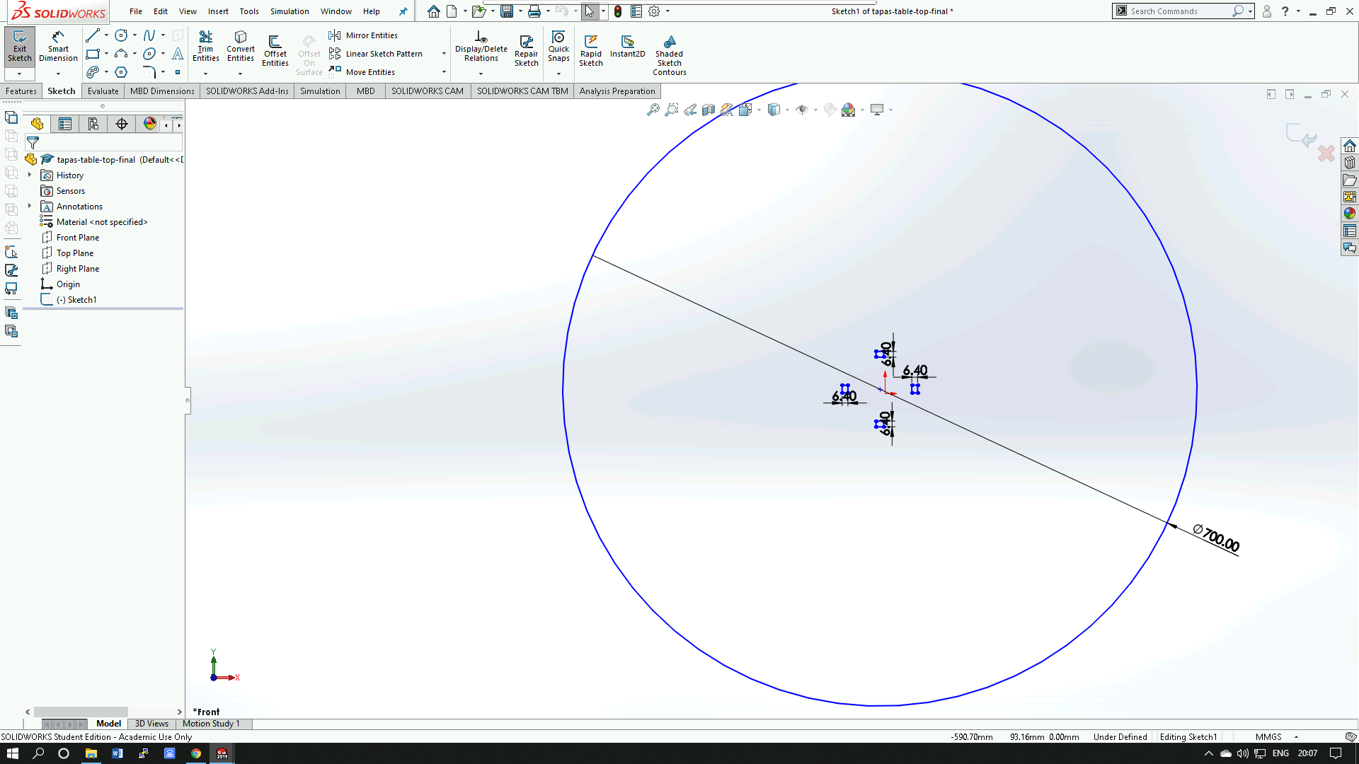
Complete the sketch drawing then exit the sketch and extruded
Setting the tool path
Before we start to mill, We have to first set the tool paths for milling various parts. In our lab we use the software 'Vcarve' for setting tool paths and to generate G-codes.
I uploaded my design which is a .dxf file into the vcarve software.
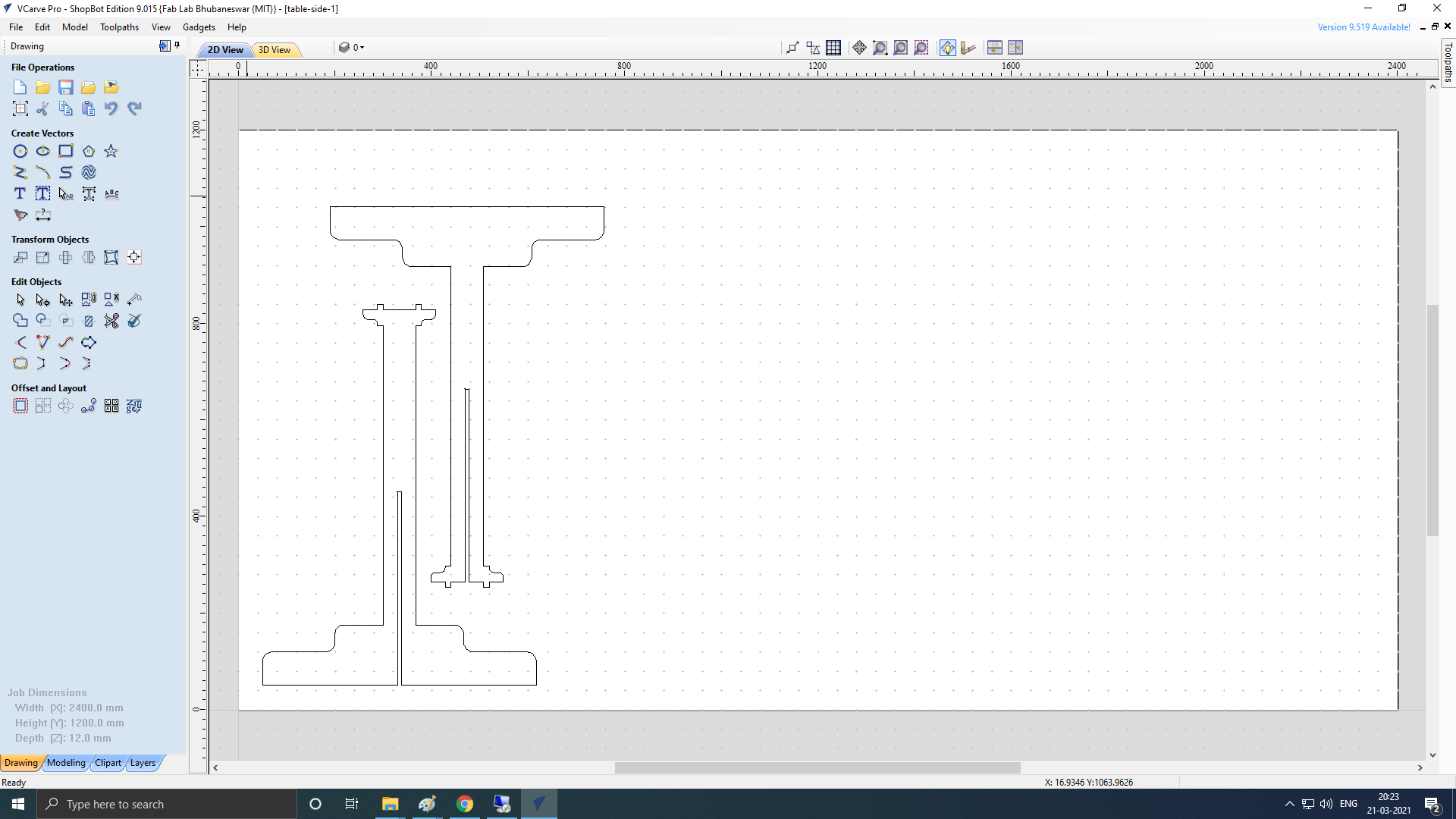
Make sure all the lines and vector paths of an object is joined. Select an object, and use the toolpath window to set the toolpath for the job.as i using 12 mm plywood so the cut depth 12.3 mm otherwise the wood will not properly cut here is i have selected on in machine vector

Add tabs to the tool path, so that the parts don't move when cutting. don't put tab in corner or at curve port of design

After Add tabs to the tool path, calculate with a profile name here is kept leg.check the tool bit setting whether it is correct or not

Reset preview and preview all tool path which acknowledge you to see the movement of bit at the time of cutting and save the file into .sbp format which will use for cut part at time of machine i have to use Screw hole - Drill holes on the plywood board for mounting the board to bed.

table top file for cutting.
Machine Setup
At this point, we have our x and y axes set to origin, now we need to set the z-axis. Use the plate on the spindle head to set the origin for z-axis. Make sure the Input lights up when making contact with the aligator clip. After that click the z-axis button and place the plate on the bed, bottom to the drill bit.
The prompts the come when using this feature; accordingly operate the prompts.
Switched on the control box, then opened the Shopbot 3 application. Its better to leave the spindle disengaged to be on the safer side.
Click on the move tool, it should give a UI similar to the below image. Use the joysticks on the UI to move the spindle to set the origin. First set the x-y position and click the zero axes button,
you will see a pop up with checkboxes for all three axes. Select the x and y axes and click ZERO.

Click to download the files :
Resources:-
https://www.instructables.com/ShopBot-CNC-Router-Class/
https://www.shopbottools.com/ShopBotDocs/files/AssemblyBinder060828.pdf
https://www.shopbottools.com/ShopBotDocs/files/ComRef.pdf
https://www.shopbottools.com/ShopBotDocs/files/DTQuickStartGuide.pdf
https://www.nasa.gov/sites/default/files/files/ARC_ShopBotTutorial.pdf
https://www.shopbottools.com/ShopBotDocs/files/SBG%2000142%20User%20Guide%2020150317.pdf
https://www.shopbottools.com/ShopBotDocs/files/QuickstartGuidePRSAlphaStandard.pdf